Tayda Enclosure UV Printing for Guitar Pedals
I have built many guitar effects pedals from Jeds Peds, who sell a bewildering array of PCB pedal kits, and has a great builder community on Facebook. The kits arrive by default with unpainted enclosures, which you can decorate yourself, and that’s part of the fun. Most people use spray painting and home-printed waterslide decals for this, but after my first batch of pedals, I decided that painting is my least favourite part of the process. It requires a level of patience and consistency that I don’t possess, is sensitive to temperature and humidiy, and makes a mess. And even with base coats, multiple colour coats, and clear top coats, my pedals all chip and ding too quickly.
There are better ways. Commercial enclosures will commonly be power-coated, which is more durable, and will have any designs printed on them directly, rather than applied via a decal. Tayda Electronics is an online electronics store from Thailand, which is popular with guitar pedal builders for supplying both components and hardware for DIY/hobby projects. And it sells both powder coating and UV design printing services. For my most recent build, I decided to use this instead of painting and printing at home.
It’s not entirely obvious how it all works, so here is my attempt at documenting the process. I learned all of this form others, in particular this tutorial from Patchyderm Pedals, this forum thread from Steggo Studios, and this video series, as well as advice and examples from David Summers of the Jeds Peds forum.
The basic idea is as follows:
- Get the PCB and components you need. Tayda does sell some PCBs, and stocks a good range of components, though in my case I got both from Jeds. (You want to order the PCB, components, and off-board components like jacks and switches, but not the “full kit” option that includes the enclosure.)
- Order the enclosure from Tayda, in the colour you want. It obviously needs to be big enough for the pedal you’re making. Enclosure sizes have funny names like 125B (a common size used by Jeds Peds in their kits), 1590BB, etc. For example here is the product page for 125B style enclosures in various colours. There are also some pre-drilled Tayda enclosures, but we will not be using those. Note down the Pantone colour name of the colour you choose from the Tayda product page - it’ll come in handy later when you work out your design.
- Order the Enclosure Custom Drill service from Tayda for the relevant enclosure type. For example, this is the 125B drilling service. This lets you ask Tayda to drill the face (for knobs and switches) and top/sides (for jack and power sockets) for you. Later, you will create a custom drill template that will let you specify precisely where the holes go and how large they are.
- Order the Enclosure UV Printing service from Tayda. This page has a lot of detail of how the service works, and you must read it all the way through, though I’ll also describe some of the pertinent points below. You basically order the relevant size of UV printing (like this one for printing on the face of a 125B enclosure), and probably also the optional gloss layer printing service, which lets you overprint a layer of shiny or matte transparent ink, giving a better sheen and some extra protection.
- Create an account on the Tayda Drill service. This is a separate webapp by the same company. You must use the same email address for the drill service account and the Tayda web store account, or you won’t be able to link your order to the drill template.
- In the drill tool, there is a web interface for creating a drill template. You can find existing ones that others have shared as a starting point, or define your own from scratch. Essentially, you place holes on a coordinate system (where
(0,0)is the centre of the enclosure) and define how big each one should be, making an allowance for the powder coating. A little while after you’ve placed your order on the main Tayda web shop, you’ll be able to link the enclosure you’ve bought to a specific drill template. - Create an appropriately formatted PDF that will be used for UV printing the design. The strong recommendation from Tayda is that you do this in Adobe Illustrator. The problem with that, is that Illustrator is expensive if you don’t already have it. Affinity Designer is a popular alternative that is more reasonable, though it is possibly more difficult to get a correct PDF out of it. I used the iPad version for my design. There are a lot of rules and nuances to getting the PDF right, and if it’s not, Tayda may at best send it back to you, and at worst print something that will look wrong. More on this below.
- Upload the UV printing PDF file in the Tayda drill tool and link it to your order.
- Wait patiently for a few weeks.
Getting the drill template right
The Tayda drill template tool lets you pick an enclosure type (which must obviously match what you’ve bought, e.g. 125B), and then add up to 40 holes. For each, you enter a diameter in mm, and an X and Y position. Note that:
- You pick the side that the holes go on, where A is the face (typically for knobs and switches), B is the top, C is the left side, and E is the right side. So depending on whether you want your pedal to have top- or side-mounted jack and power sockets, you need to pick the right location.
- If you are getting the enclosure powder coated (or if you are going to paint it yourself later) you need to add 0.2mm to the size of each hole, because the powder coat will get inside it. They drill first and coat later!
- The X Y position is based on a coordinate system where
(0,0)is dead centre of the enclosure. So a position of(10,15)is 10mm to the right of the vertical mid line, and 15mm above the horizontal mid line.(-10,-15)would be 10mm to the left and 15mm below the centre.
You can also use the “line” option in the drill template tool to make non-circular cutouts (think square power sockets or sliding EQ knobs), though I’ve not had a need for these.
Here is what the drill template tool looks like:
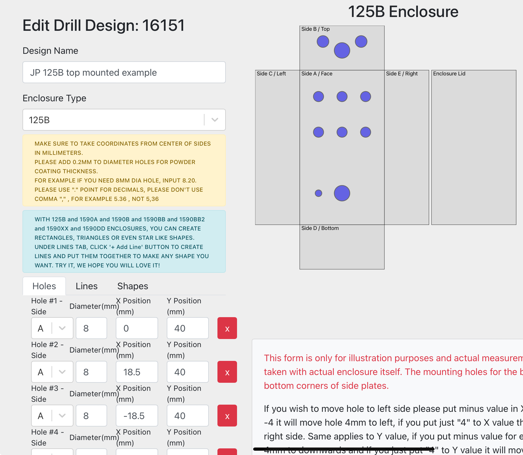
Entering the template is relatively straightforward, but deciding the exact position of each hole might not be. This is where finding some examples might help, and the PedalPCB forum contains a bunch. You need to be logged into the drill tool first, and then you can click one of the links to get a template someone else has shared pre-loaded into the editor. Save it as your own and it’ll make a useful starting point.
Most of the Jeds pedals come with PCB-mounted pots and switches. What that means is that the pots and switches are soldered directly onto the PCB, not connected with short wires. This makes installing the circuit into the enclosure easier, but it means you have to be very precise with where the holes for your pots (knobs) will go. If you wire in the components, they are more fiddly to install, but you have more freedom over exactly where they are positioned. Short, solid-core wires that have some rigidity to them are good for this type of job.
Unfortunately, there is no absolute standard for Jeds Peds layouts, though here are some examples to illustrate the types of layouts you may come across:
- 125B with six holes for knobs and switches and top-mounted jacks
- 125B with narrower spacing and side-mounted jacks
- 1590B with side-mounted jacks
Again, please remember to measure your actual kit as it may not match any of these layouts!
Another thing to think about is how much space there is inside the enclosure. A large PCB, with many pots and switches, will have less room for error, because you might end up with a pot getting in the way of a jack socket or a switch not fitting between two knobs. Careful measurement is the key, since the Tayda drill service has a long lead time. Unless you’re confident, I’d recommend buying the PCB and controls first, building the guts of the pedal, and then checking your measurements. Or even ordering the Jeds pre-drilled enclosure and take measurements from it, even if you aren’t using it.
Getting the design PDF right
Before we get into some specifics, let’s talk about some of the gotchas and quirks of making a design for UV printing.
- The PDF must use CMYK colour space, not RGB.
- The PDF must be the exact dimensions of the enclosure, in mm. The Tayda UV printing guide has the expected sizes and template files you can use. For 125B, for example, that is 62mm wide and 117mm tall.
- Nothing can be placed outside the edges of the file, i.e. you need to delete or crop anything that goes off the side of your file.
- Everything in the design must be vector graphics, so:
- You can add text with whatever font you want, but before exporting the file, you need to convert them to paths (or “curves”, as Affinity will call them), which really just means each letter becomes a separate vector shape. At this point, the text is no longer editable as text, so you will usually do this at the end.
- If you want to use clipart or bitmap images (like PNG, JPEG, or GIF files), you need to vectorise them first. This can be a little hit and miss, but Vectorizer.com seems to do a decent job of it for free. Simpler, cleaner designs will generally work better.
- Your main design needs to live entirely in a single layer named “COLOR”. You can use other layers during the design process, and this can be useful for previewing the design (e.g. to show the true background colour, the positions of knobs and switches, etc.), but you have to hide them before exporting so they are not in the main PDF.
- Nothing can overlap in each of your exported layers. You need to flatten and modify vector shapes so that they don’t. (This is to preserve colour representation, apparently, and though I suspect there are instances where it’s not necessary to follow this rule, Tayda is pretty unequivocal about it, and it didn’t seem worth the risk to try something else.)
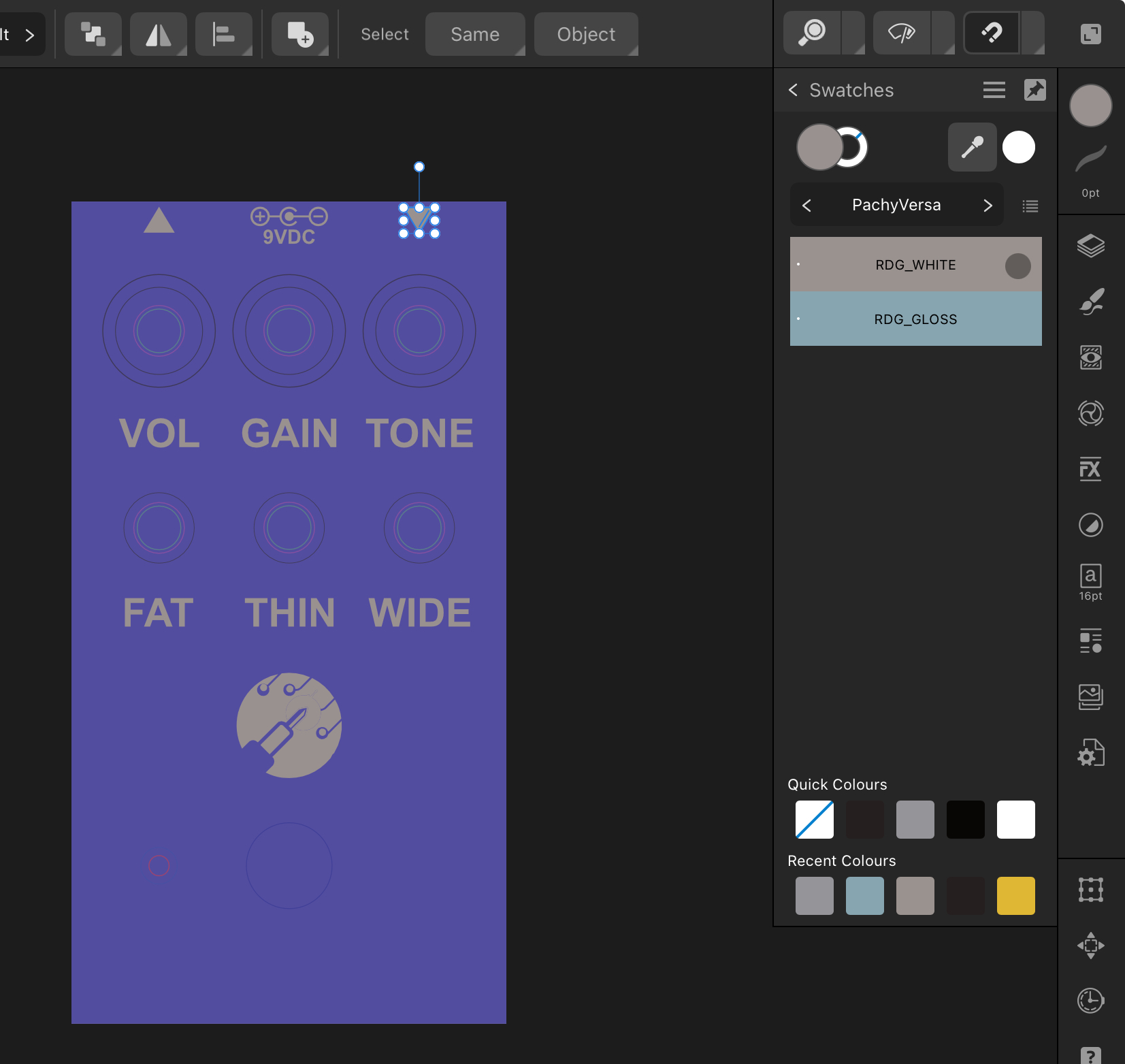
- Most printers can’t print white. The UV printer can do so, but only in a special layer, which must sit beneath the “COLOR” layer and must be called “WHITE”. To tell the printer to do so, you don’t actually submit something that will look white on your screen. Instead, you use a special “spot colour” called
RDG_WHITEfrom a special “Roland” swatch, which looks gray, but comes out white. (In CMYK, this colour is(25, 25, 25, 25)). If you want something to look white, you need to draw it in the “WHITE” layer and then ensure nothing in the “COLOR” layer obscures it. - You often need a white “base coat” underneath your actual design, even if the final colour isn’t meant to be white. This is because a printer generally assumes it is printing on a white background. So if you are printing “light yellow”, it deposits a little bit of yellow on top of the white, and if you are printing “dark yellow” it deposits a bit more. But if your powder coating is not white, this can turn out very different (blue + yellow = green, for example). The solution is to paint in white first on the “WHITE” layer, and then the intended colour in the exact same spot on the “COLOR” layer above it. A common way to do this is to first create your design in the “COLOR” layer and then copy every element to the “WHITE” layer and change the fill colour to the
RDG_WHITEcolour. Note that you cannot have other colours at all in the “WHITE” layer, so you may need to worry about any lines or fills or gradients. - Something quite similar happens with the gloss finish, if you ordered this. You create a layer on top of the “COLOR” layer called either “GLOSS-V” (for a shiny gloss) or “GLOSS-M” (for a matte one), copy the shapes you want to apply the gloss finish to into this layer, and change their colour to
RDG_GLOSSfrom the Roland swatch. (The CMYK spot colour is(50,25,25,0).)
(I’m articulating the layer names as gospel here because that is what Tayda says to do, though I have a suspicion it might work with different names too. But why take the risk?)
Now let’s talk about Affinity Designer. It’s an app that works on most platforms, including iPadOS, and can be bought for a reasonable one-off fee. I don’t know if it’s as good as Illustrator, but it worked well for me and was reasonably intuitive. In practice, the approach you might take to complete a design using Affinity Designer would be:
Import the Roland “spot colour” swatches for white and gloss. There are a few floating around, but I used the “PachyVersa” palette from the Pachyderm tutorial and imported it as an Application palette in Affinity. More on that process here. With this installed, you can pick the relevant swatch in the Affinity colour picker to get the right colours.
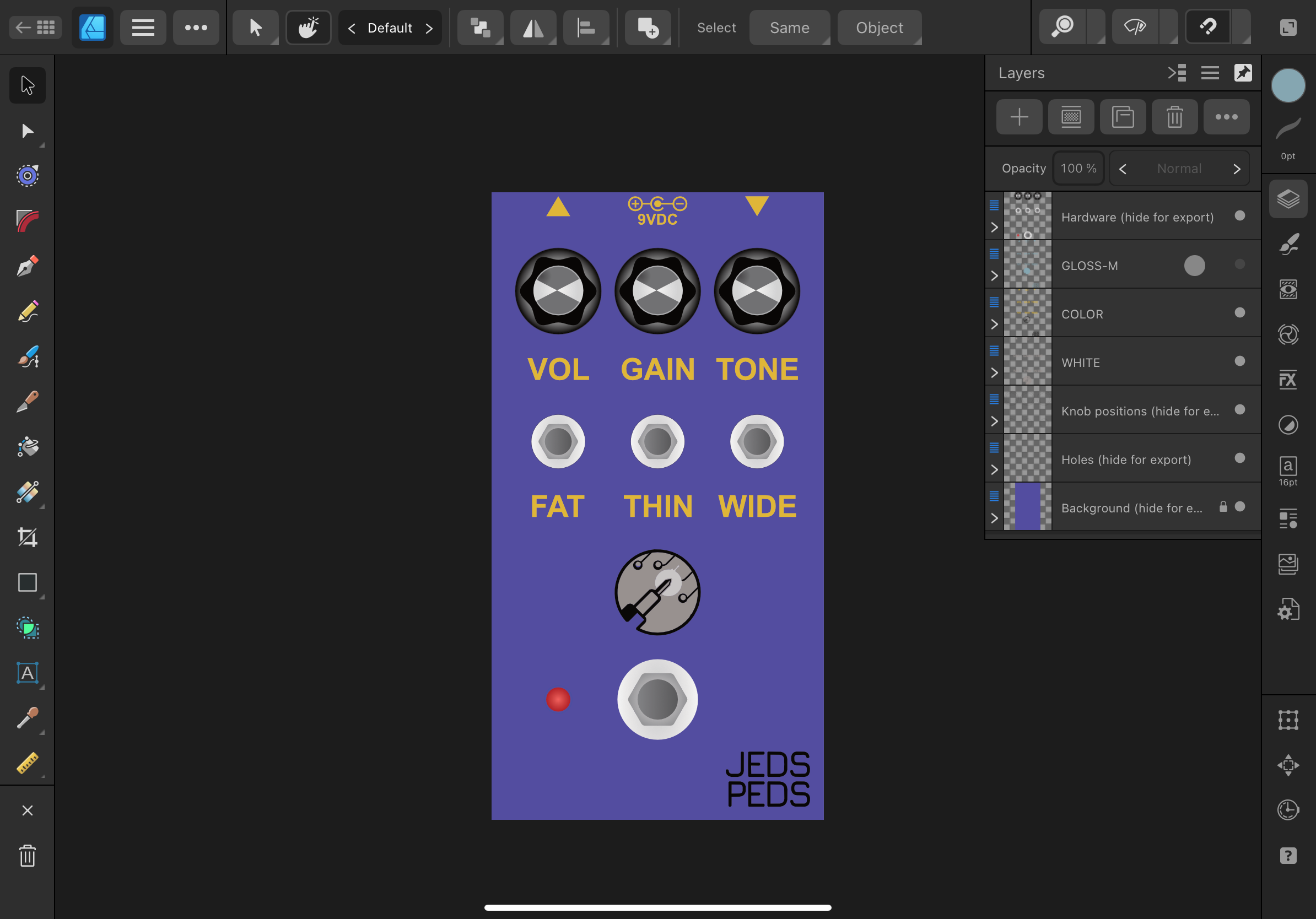
Start with a template that sets up the right artboart dimensions (e.g. 62x117mm for a 125B enclosure) and layers. I began the “Tayda 3 Knob” one from this page by Pachyderm pedals, downloading the Affinity Designer file, though below I’ll share an example that aligns to one of the Jeds Peds 125B drill templates above. You could start from scratch with a blank file too, of course, but the templates here are useful because they illustrate a lot of good practices in terms of layer and colour management.
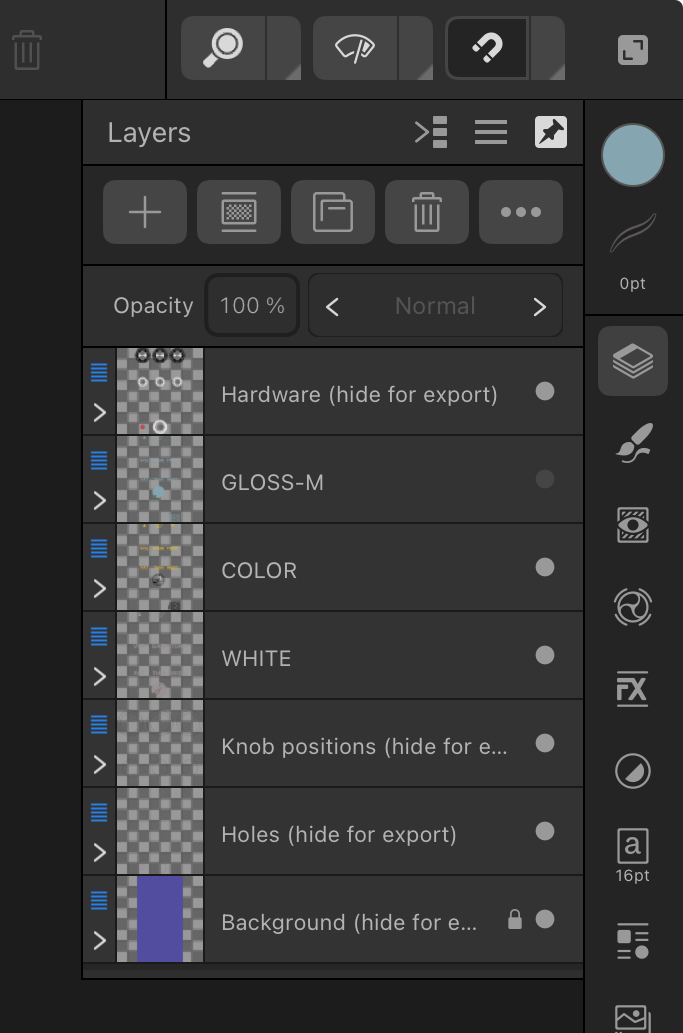
The example template sets up a “background” layer at the very bottom that’s just a square in the colour of the enclosure. This won’t be included in the final export, but it’s very useful to get a sense of how the design actually looks. You can use the Pantone swatch in Affinity designer to pick the correct Pantone colour for your enclosure if you ordered it painted from Tayda.
On top of this, there are other layers that draw the positions for drill holes, outlines of knobs and switches, and more stylised images that show how knobs and switches might actually look. Again, these layers are not used by Tayda and must be removed from the final PDF export, but they are useful aids to make sure the layout will work in practice.
In-between these helper layers, we have the “WHITE”, “COLOR”, and “GLOSS-M” (for matte) or “GLOSS-V” (for shiny varnish) layers where the design itself will go.
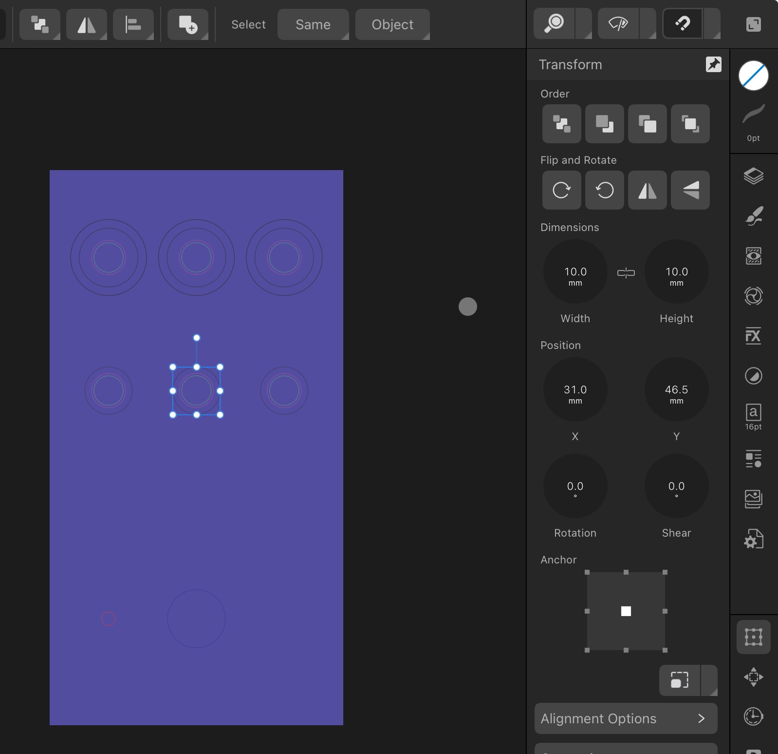
The next step is to make sure the markers for drill holes, knobs, and switches are in the exact same place as they are on your drill template. In Affinty Designer, the Transform panel lets you enter a specific position and size for a selected object, in mm. When you do this, you first want to lock aspect ratio under Dimensions so height and width are changed in proportion, and choose the centre Anchor point, so that when you update the position X,Y coordinate, you are moving the centre of the shape, not the top-left corner. (The Tayda drill template tool does the same thing, i.e. the coordinate you enter is the centre of the hole, though it is not the same coordinate system - see below.)
Getting the size right is pretty straightforward. For example, if you are planning to use 22mm knobs, you set the dimensions on the knob graphic in the relevant layer to 22mm. (This is optional of course - you don’t be exporting those graphics, but they help finalise the design.) If you want to draw the exact holes that will be drilled (which may or may not be needed, given knobs and switch nuts will be larger than the hole anyway), you can use the diameter specified on the drill template.
However, getting the X,Y position correct requires a little bit of maths. This is because the Tayda drill template coordinate system treats (0, 0) as the centre, but Affinity will treat (0, 0) as top left on the enclosure. (I believe Illustrator has an option to change the canvas grid system so that the origin is at the centre, but I could not find such an option in Affinity Designer on the iPad.) The translation can be done like so, assuming a 125B 62x117mm enclosure:
Tayda X = -18.5mm
Tayda Y = 40mm

Enclosure width = 62mm
Enclosure height = 117mm

Affinity X = (Enclosure width / 2) + Tayda X => 12.5mm
Affinity Y = (Enclosure height / 2) - Tayda Y => 18.5mm
(I use an iPad app called “Calca” to do this very thing dynamically from the text above. You could use a spreadsheet too, of course.)
Here, the Tayda point of (-18.5, 40) will be towards the top left of the enclosure face side. The equivalent Affinity coordinate would be (12.5, 18.5). This is what you’ll enter on the Dimensions panel in Affinity.
Next, create the required design on the “COLOR” layer. Simple is usually better. Leave the background colour and knob/switch layers visible (perhaps locked) while you do this, so you can see how your design will actually look when the pedal is assembled.
Everything has to be a vector. If you want to import a file that’s shared as JPEG, GIF, PNG or similar bitmap image, you will need to vectorise them first. I had the best result using this online service, importing (“placing”) an SVG file, and then copying the relevant curves from the SVG “out” of the nested object, so they lived directly on the “COLOR” layer, before making further edits. (I’m unsure if a nested/embedded SVG will print correctly.)
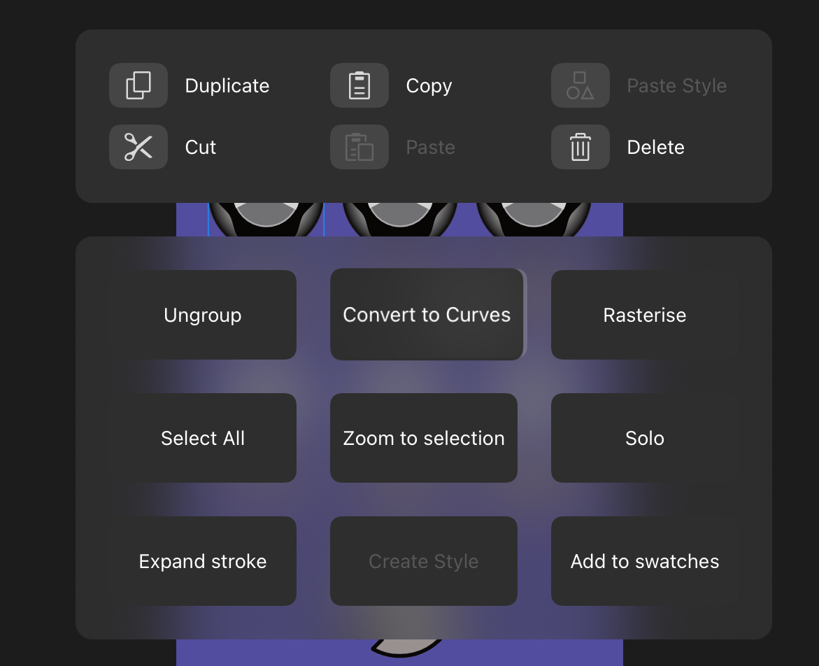
You can right-click (two-finger tap) on a shape in Affinity and choose Convert to Curves to turn sub-layers into top-level shapes, which I have read makes it more likely Tayda will be able to print the design. You need to do the same for all text boxes prior to export, so that the text is represented as vector lines rather than embedded text. Without this, I suspect the Tayda printer would attempt to print the text, but might get the font wrong, leading to an incorrect design.
No shapes should overlap. If you have a shape on top of another shape, you need to create a “cutout” in the underlying shape. The Tayda UV printing instructions talk about this (look for cats and houses), but the way I most effectively managed to do this in Affinity was a little dance of: Select the top shape. Copy to clipboard. Select both top and bottom shapes. Use the Affinity Geometry toolbar (at the top when using the standard selector tool) to subtract the shapes, which should leave a gap in the bottom shape. Immediately paste the copied object back so it slots into place. Rinse. Repeat. A bit fiddly, but works fine.
If you want white coloured text or lines, you need to do this on the white layer only, using the special RDG_WHITE spot colour, and leave a gap on the “COLOR” layer. You may want to leave it on the “COLOR” layer in (actual) white first and then delete this towards the end, since the RDG_WHITE colour doesn’t actually look white on your screen.
Once you’ve got the design you want on the “COLOR” layer, it’s time to create any white undercoat you need for colour correctness. The simplest option is just to copy everything from “COLOR” to “WHITE”, temporarily hide the former, and then change the fill colour to the RDG_WHITE colour from the Roland swatch. It’ll look gray on your screen, but it’ll print white. It’s important that everything in this layer is this colour, including lines and fills and the contents of groups. If you have a complex but continuous shape made up of several objects and paths, you may want to select all the elements and use the Geometry toolbar to Add all the shapes together into a single path, which will be easier to colour. Turn the “COLOR” layer back on, and the “WHITE” layer contents should be fully hidden underneath it, save for any “gaps” you’ve left for true white content.
The “GLOSS-V” (shiny varnish) or “GLOSS-M” (matte) layer can be made in a similar way. Copy everything you want to make glossy, paste it into the gloss layer, and change the color to RDG_GLOSS, which will look a blueish gray and will cover the “COLOR” layer contents fully, unless you want to leave some bits unglossy. (Conincidentally, I’ve wondered if it would be a good idea to just cover the whole design with a gloss square to coat all of it, but I believe this would leave slight height differences across the design and it just doesn’t seem to be the way others have done it, so I never tried.)
Once you’ve done all this, it’s time to export. First, you need to hide every layer in Affinity Designer other than “WHITE”, “COLOR” and “GLOSS-V” or “GLOSS-M”. You should now see the transparent background grid and the gloss spot colour, with the colour and white layers hidden underneath as applicable. Double check that you have made everything on each layer into curves (including text and groups) and that none of the drill hole, knob, or background colour layers are visible. Then export as PDF. There are a bunch of options, but the ones I used are:
- PDF 1.7 compatibility
- “Include layers” (very important)
- “Honour spot colours” (also very important)
- CMYK colour space (though “as document” should still produce CMYK if you set up the file correctly)
At this point, you may want to check the exported PDF. If you re-import it into Affinity Designer, you should see a document that has the right dimensions, with exactly three layers, and all your white, colour, and gloss content on it, with all text embedded as shapes, not actual text and fonts. The PDF background might look white instead of transparent, but this is fine.
You could check this again in Adobe Acrobat Reader, which should also show the same layers. Note that if, like me, you try to get someone to check it in Adobe Illustrator, the layers will be gone. I believe this is because of a limitation of Illustrator’s PDF import, rather than Affinity Designer, and that it won’t matter.
Once you’re happy, you can upload this template under UV Print Templates in the Tayda Drill Tool. You’ll be asked a series of questions that are designed to make sure you’ve followed the instructions correctly. The template will then be on your account and ready to be used.
Here are example Affinity Designer and PDF export files that uses the first 125B layout above, showing three knobs and three switches. All the techniques above are demonstrated here.
DISCLAIMER: I have not tested this exact file with Tayda. It is closely based on a design I did get drilled, painted, and printed, but it is possible I have made a mistake somewhere. Do your own checks, and use at your own risk. I am sharing it mainly to illustrate the process!
- I started by setting the background colour on the background layer, before locking that layer.
- Next, I adjusted the size of each of the drill holes, knob guides, and hardware visuals in the relevant layers, using “centre” anchoring and translating the positions and sizes directly from the Tayda drill tool using the calculation above. (If you have another design with a similar layout but perhaps fewer knobs, you could use this as a starting point and delete the bits you don’t need. Just remember to measure, as even another six-hole design could have different spacing.)
- I added text labels using the font tool and careful positioning. Once I was happy with the text, I converted it to curves (paths), so it is no longer editable, but should print correctly.
- I found a PNG file of the Jeds Peds logo and converted it to SVG using Vectorizer.com. After importing (“placing”) this in Affinity Designer, I double-clicked into the image and copied all the shapes, before exiting the SVG editor, deleting the image, immediately pasting the shapes back, and then grouping them. This way, the shapes are actually found directly on the Affinity file, not nested inside the SVG.
- The vectorised image had several areas with white or gray shapes on top of black shapes. Double-clicking into the group now comprising the logo, I used the “copy, subtract, paste” dance described above to make sure nothing overlapped (i.e. if I had deleted any individual shape, I’d see the background coming through). Note that at this point, I still had white shapes on the “COLOR” layer.
- To make the white layer, I hid the hardware and guide (holes, and knobs) layers, copied everything from the “COLOR” layer except the black text in the bottom corner, hid the “COLOR” layer, moved to the “WHITE” layer, and pasted the shapes there. Then I selected all the elements and changed their fill colour to the “RDG_WHITE” colour from the Roland swatch. At this point, everything other than the background looked uniformly gray, with no lines or other colours.
- I repeated this in the “GLOSS-M” layer, but this time I included the black text (which does not need a white undercoat but does need matte gloss on top). I selected all the shapes inside the group with the logo and used the “Add” function under “Geometry” to make a single, contiguous shape before setting the colour of this and the textual elements (earlier converted to curves!) to “RDG_GLOSS”, which shows up a blueish colour.
- I still had white content in the “COLOR” layer, specifically inside the Jeds Peds logo. With both the “COLOR” and “WHITE” layers visible, I edited the group on the “COLOR” layer to delete the white shapes, confirming that the grayish “RDG_WHITE” would show through.
- At this point, I turned all the layers back on to confirm that everything aligned properly. With the “GLOSS-M” layer selected, everything was coloured uniformly in “RDG_GLOSS”. Turning that layer off, the colours would come through though the whites still looked like the grayish “RDG_WHITE”. With the “COLOR” layer hidden, everything was “RDG_WHITE”.
- I then hid all layers except “WHITE”, “COLOR” and “GLOSS-M” and exported to PDF, making sure to use CMYK, including layers, and honouring spot colours.
- Finally, I re-imported this PDF into Affinity Designer to confirm the three layers were present and that the design otherwise looked as expected.
Uploading and creating jobs
The final step is to check out and pay for your Tayda order, if you haven’t already, and then look for it in the Tayda drill tool (which will take 15+ minutes to show up). You will be led through a series of screens where you will associate each physical enclosure and item of the “custom drill”, “UV print” and “gloss print” services in your order, with specific drill and UV templates. Tayda has some strong warnings that you need check and double-check everything, because once you submit, there can be no future amendments or changes.
Then you wait! :)
Your job will appear in the drill tool and over time the various parts (drill, paint, and print) will show updated statuses. It’s a good idea to check back periodically: I believe Tayda may report errors on the drill tool dashboard but won’t email you if something is wrong.
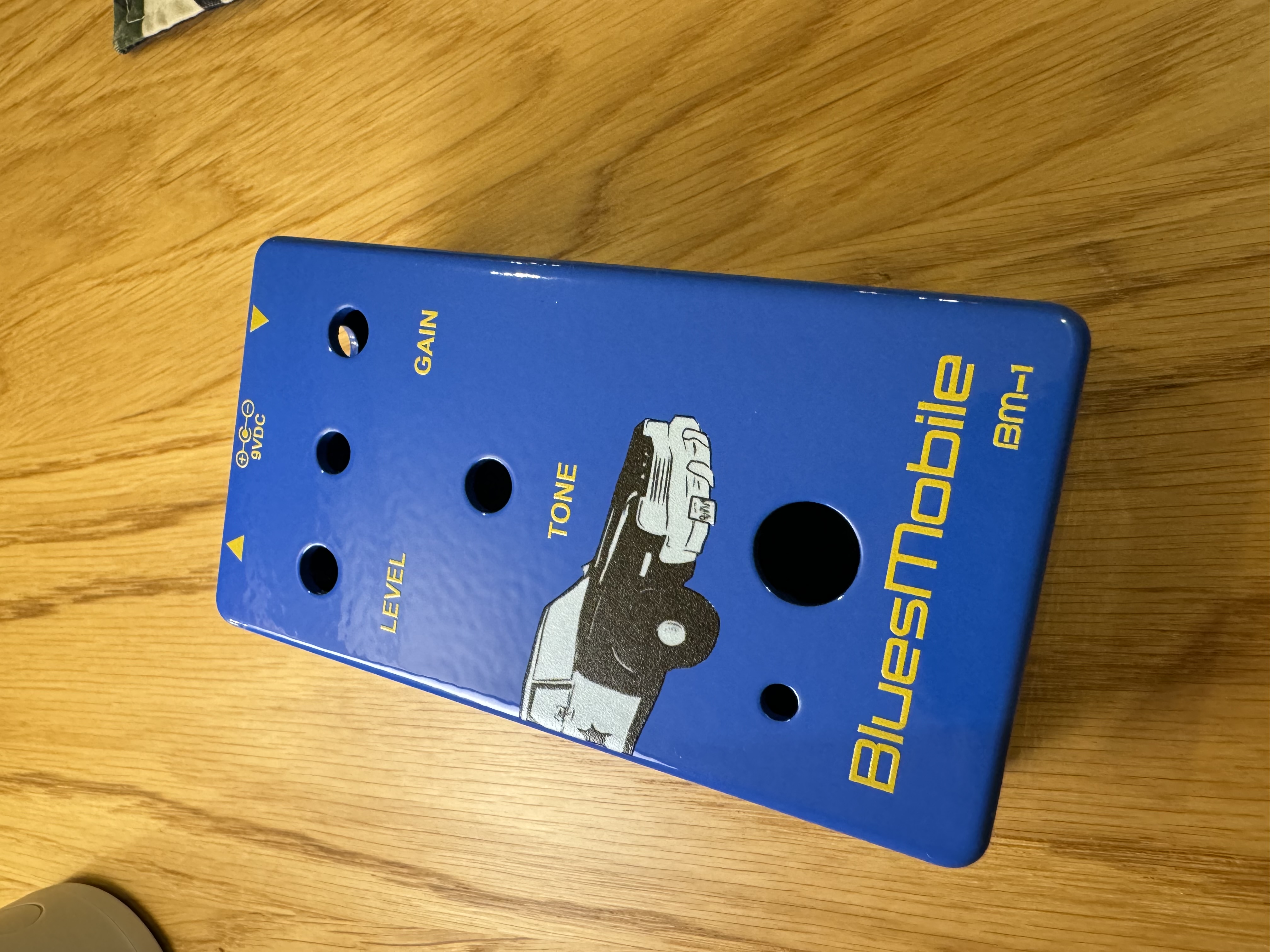
After a while (it took a little over a week for me), you will hopefully receive a shipment notification that lets you know your order is on the way. And if all went well, it might look a little like this: